-
The SFR module is capable of testing the resolution of images and quantifying indicators such as sharpness, sharpness, and chromatic aberration. It is one of the most important test methods in image quality analysis.
Select the ISO-12233-2000 test card thumbnail on the homepage, as shown below:
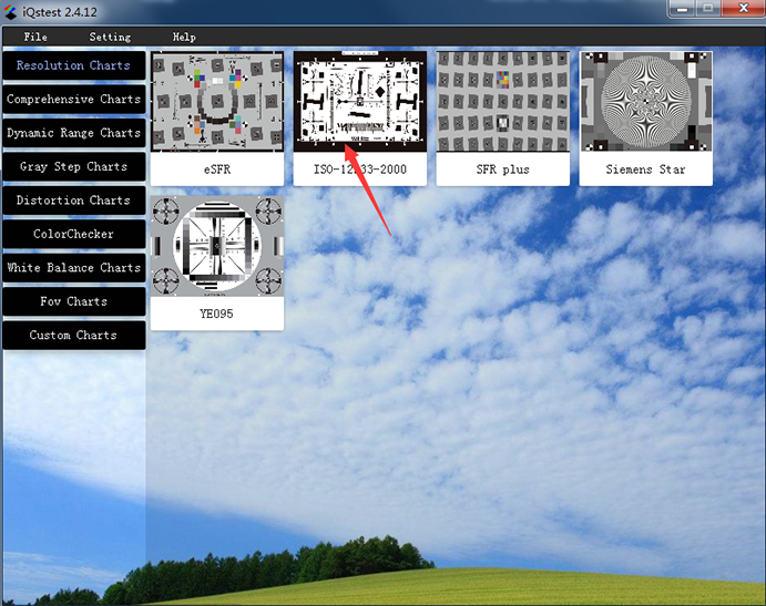
Figure 3.1.1 Selecting a test cardClick on the thumbnail to display the following configuration:
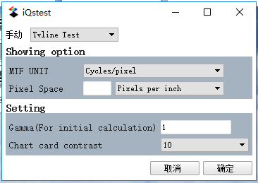 Figure 3.1.2 SFR Configuration Page
Detailed configuration:
The SFR configuration is divided into 5 sections (Figure 3.1.2):
1. Test module selection;
2. Display options: MTF units have cycle/pixel, cycle/inch, cycle/mm, LW/PH, LP/PH, etc. If the MTF unit is set to cycle/inch or cycle/mm, the pixel size must be set. There are three ways to specify the pixel size: 1) the number of pixels per inch; 2) the number of pixels per millimeter; 3) the micron size of each pixel;
3, set the parameters; the parameters set here directly affect the results, each parameter has a given default value. For example, the gamma default for SFR is 1, and the graphics card contrast is 40:1;
4, drawing selection; by tick, you can control the display of the results;
5, optional parameters; mainly image information, can be used for output of results;
After the configuration is complete, click "确认", the file selection box will pop up:
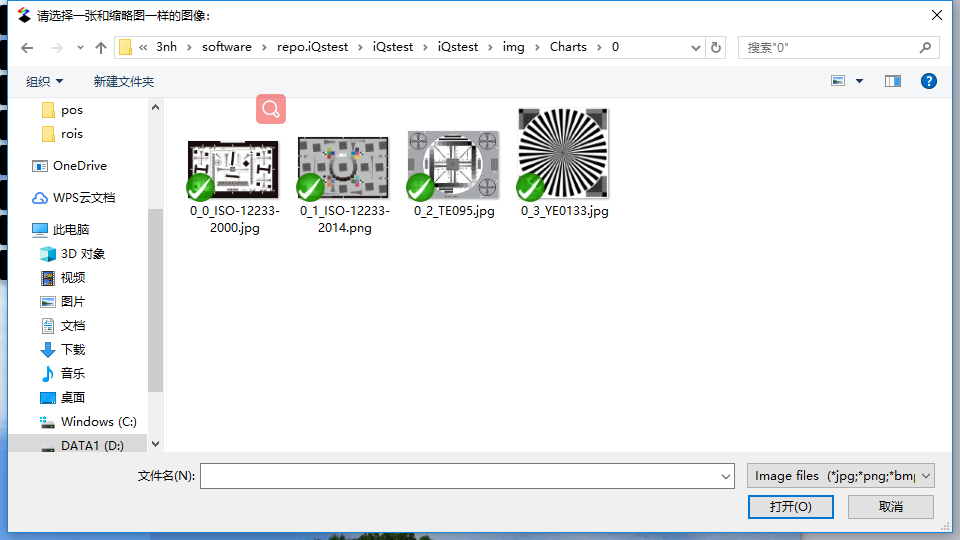 Figure 3.1.3 Test Image Import
Select the image file for analysis from the local, click "Open", you can open the image file to be analyzed, as shown below:
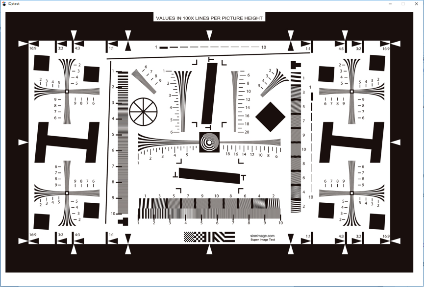 Figure 3.1.4 ROI area selection
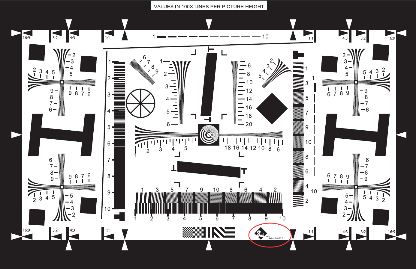
In the area of the image, you can select a roi area by dragging the mouse. Note that there is a certain standard for the selection of the SFR's roi. The standard diagram is as follows:
 Figure 3.1.5 Standard SFR
When roi is selected, release the left mouse button and the following analysis box will pop up automatically:
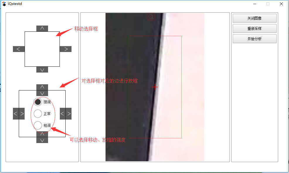 Figure 3.1.6 ROI area fine-tuning
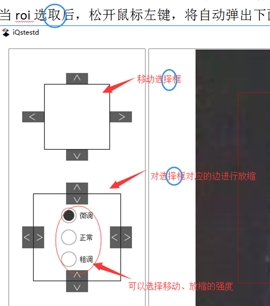
In the above picture, the left side is the fine-tuning function area. By clicking the button above (providing three kinds of fine-tuning: fine-tuning, normal, coarse adjustment), the roi can be moved and scaled so that the cross mark in the middle of the roi falls to the edge of the hypotenuse. . Then click the “Start Analysis” button, the software will call the module for analysis and present the results. For detailed results, please see the next section.
Result display
After clicking the “Start Analysis” button, three pages pop up, arranged in the following way, namely LSF Curve, ESF Curve, MTF Curve (curve: curve).
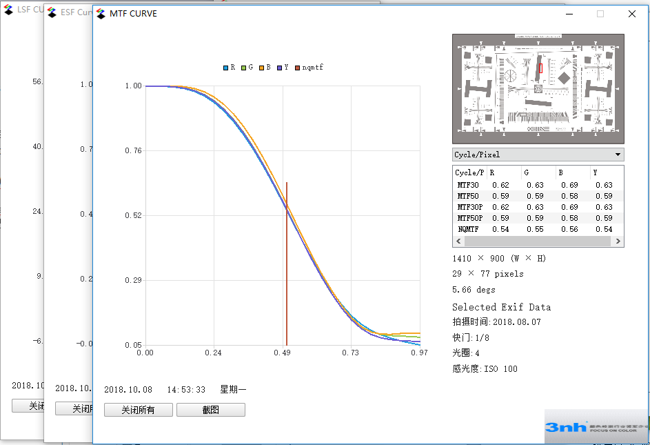 Figure 3.1.7 Results presented
The results are combined with curves and graphs. The important indicators of SFR are listed in the chart on the right: MTF30, MTF50, MTF30P, MTF50P, CA, 10~90% rise, etc.
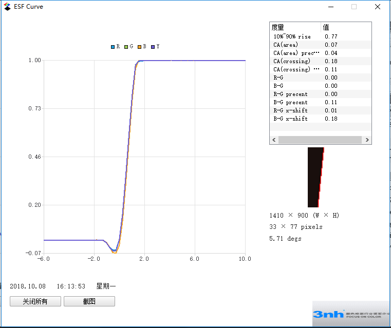 Figure 3.1.8 ESF curve indicator
From the table in Figure 3.1.8, the color difference CA, the 10~90% rise index, and the ROI oblique line straight line fit can be obtained. As can be seen from the figure, the line fit is very high.
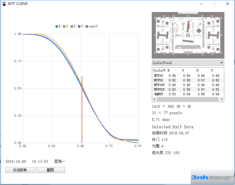 Figure 3.1.9 MTF Curve Indicators
Figure 3.1.9 plots the MTF curve of the hypotenuse. From the curve we can get the spatial frequency corresponding to different MTFs (the unit can be switched);

Figure 3.1.10 Indicators (divided into RGBY, corresponding to red, green, blue and gray)